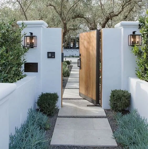
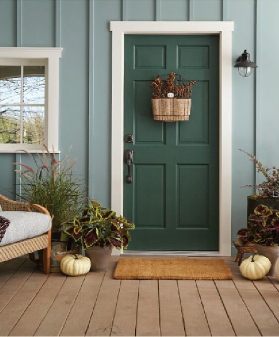
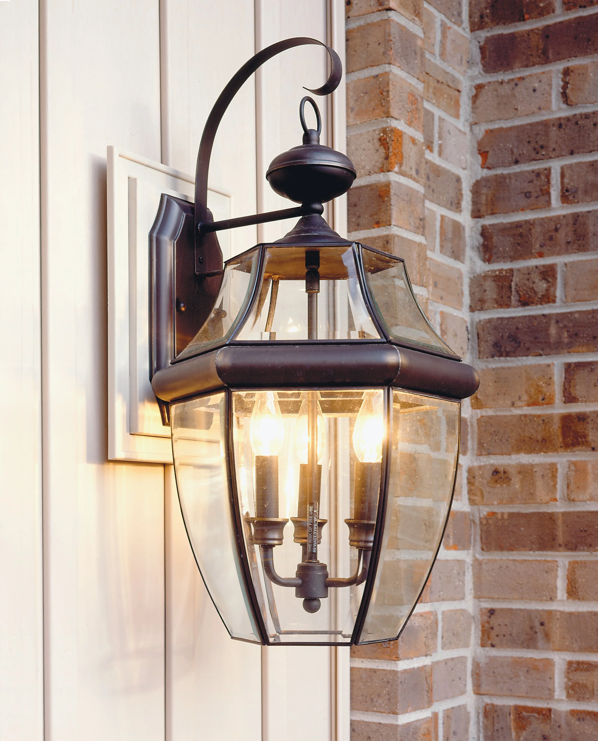
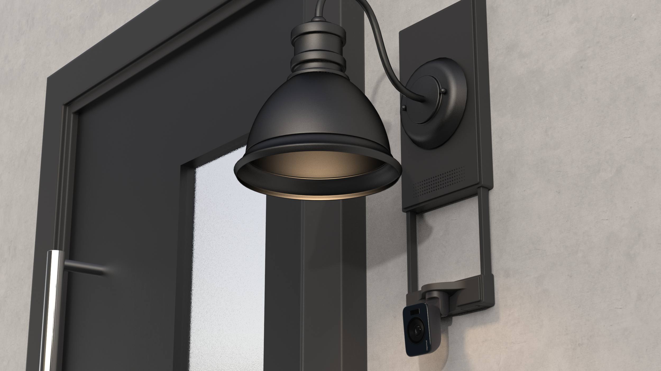
CAMERA WALL PLATE
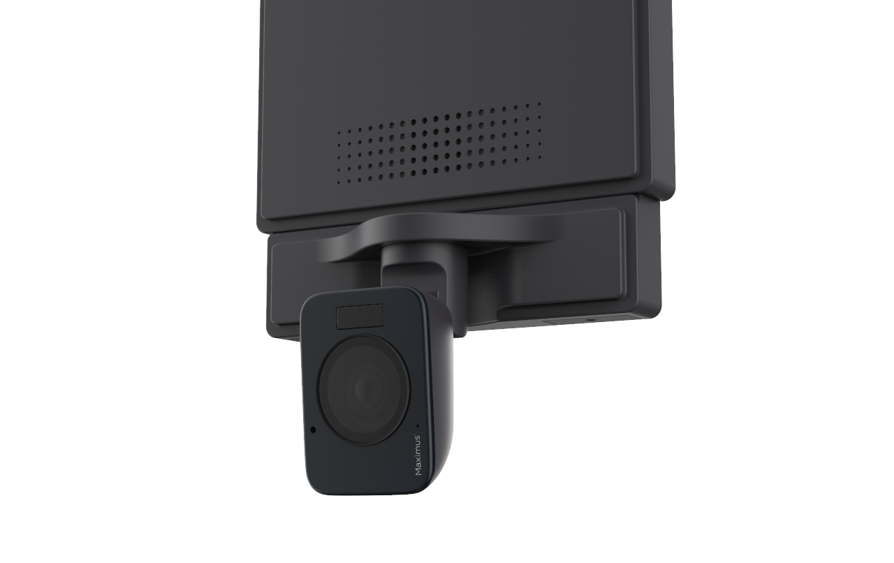
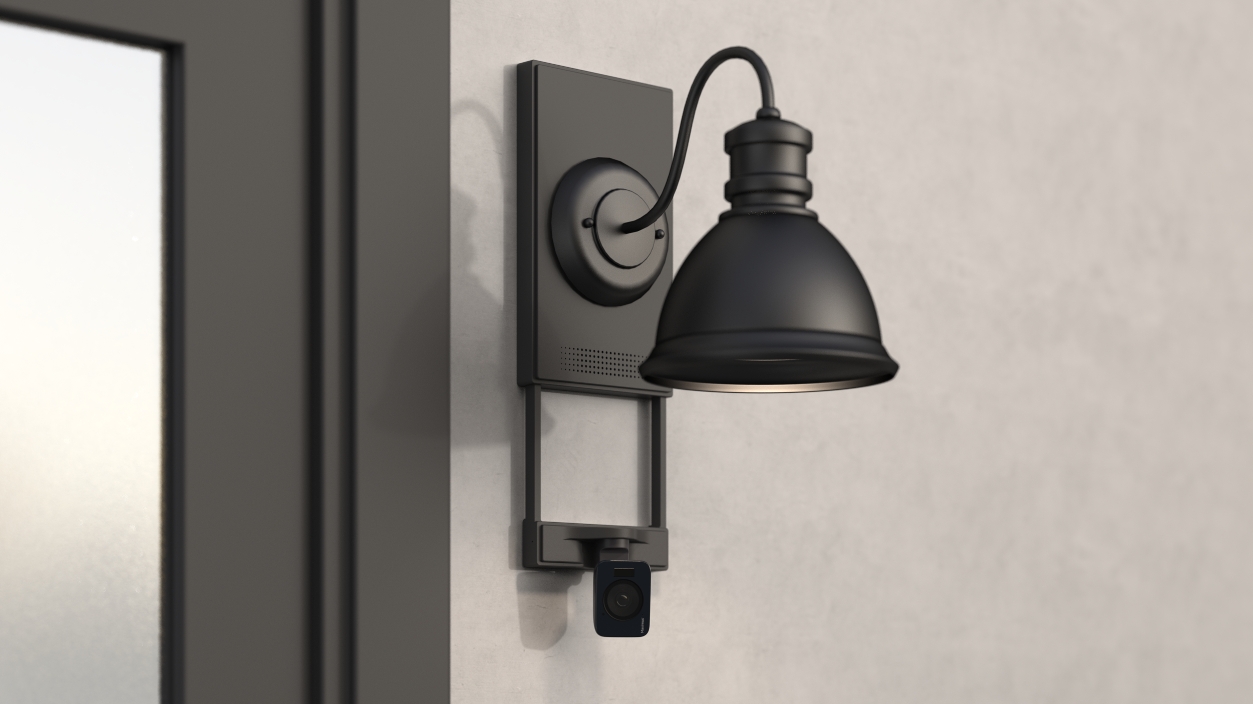
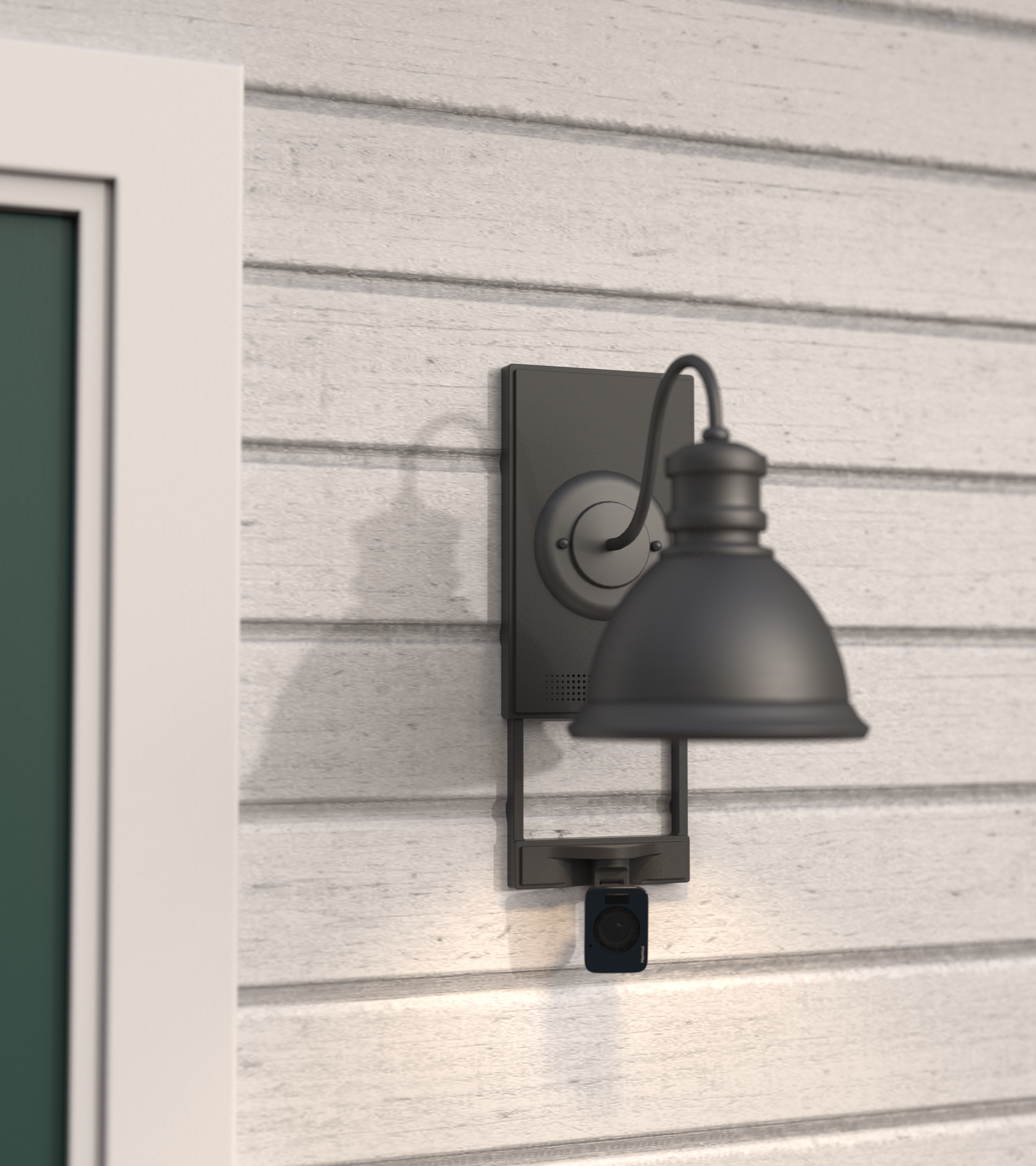
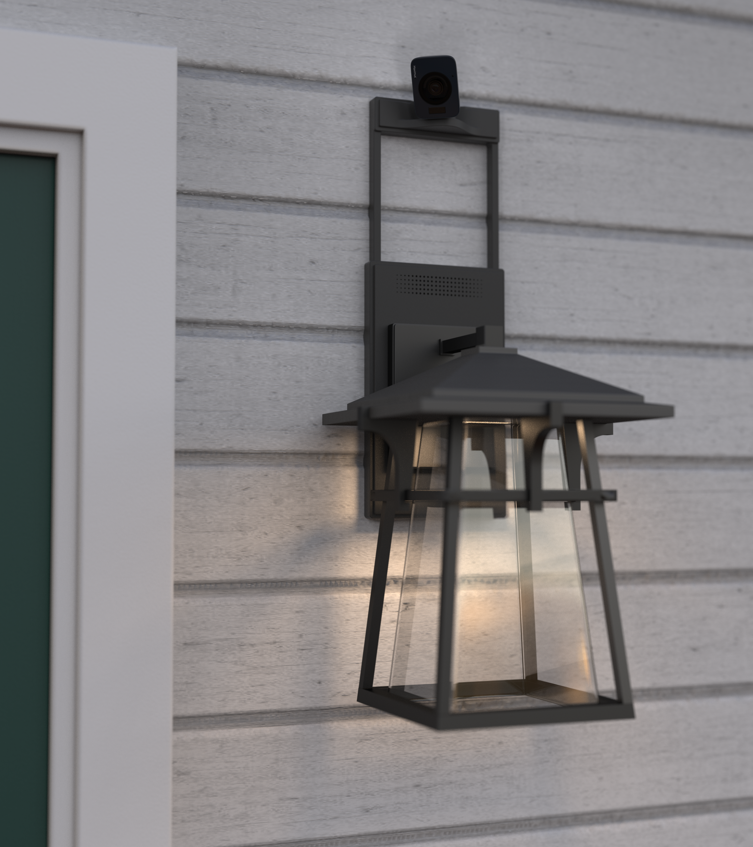
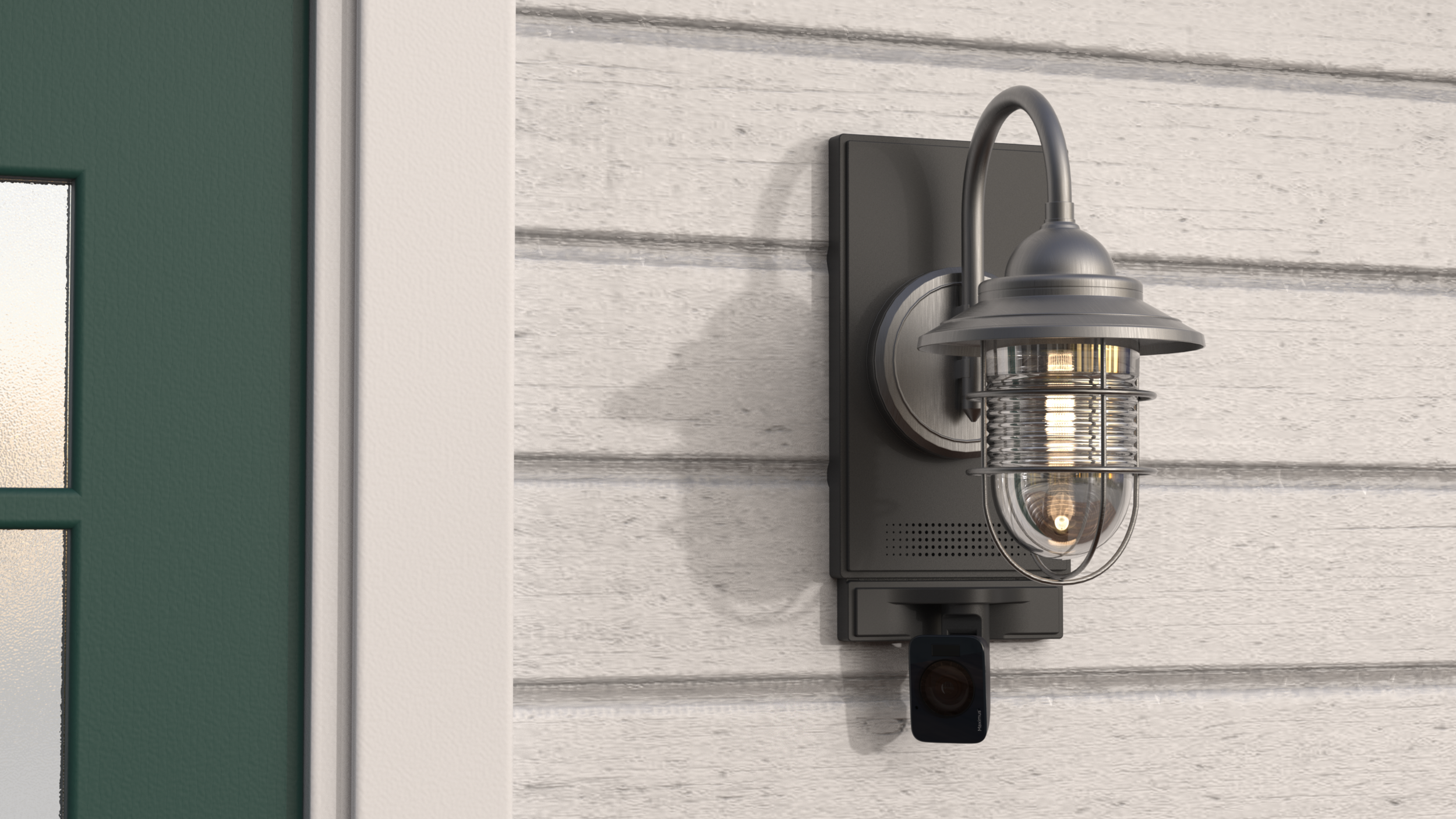
Collaborated with Maximus to design the first wall plate with a camera and adjustable arm. It’s compatible with different home decorations and wall lights at Home Depot.
MY ROLE
I contributed in the ways of marketing research, problem-solving, concept sketching, rough hand prototyping, CMF selection, 3D modeling, and visualization.
Client
Kuna (Maximus), via Deap design
Role
Lead industrial Designer
Phase
Research / Concept Development / Design Development / Manufacturing Support / Visualization
Credits
Anna-Pia (Design Direction)
Erich (Design Direction)
Yasmin (Industrial design)
Status
2019 Design / 2023 Release
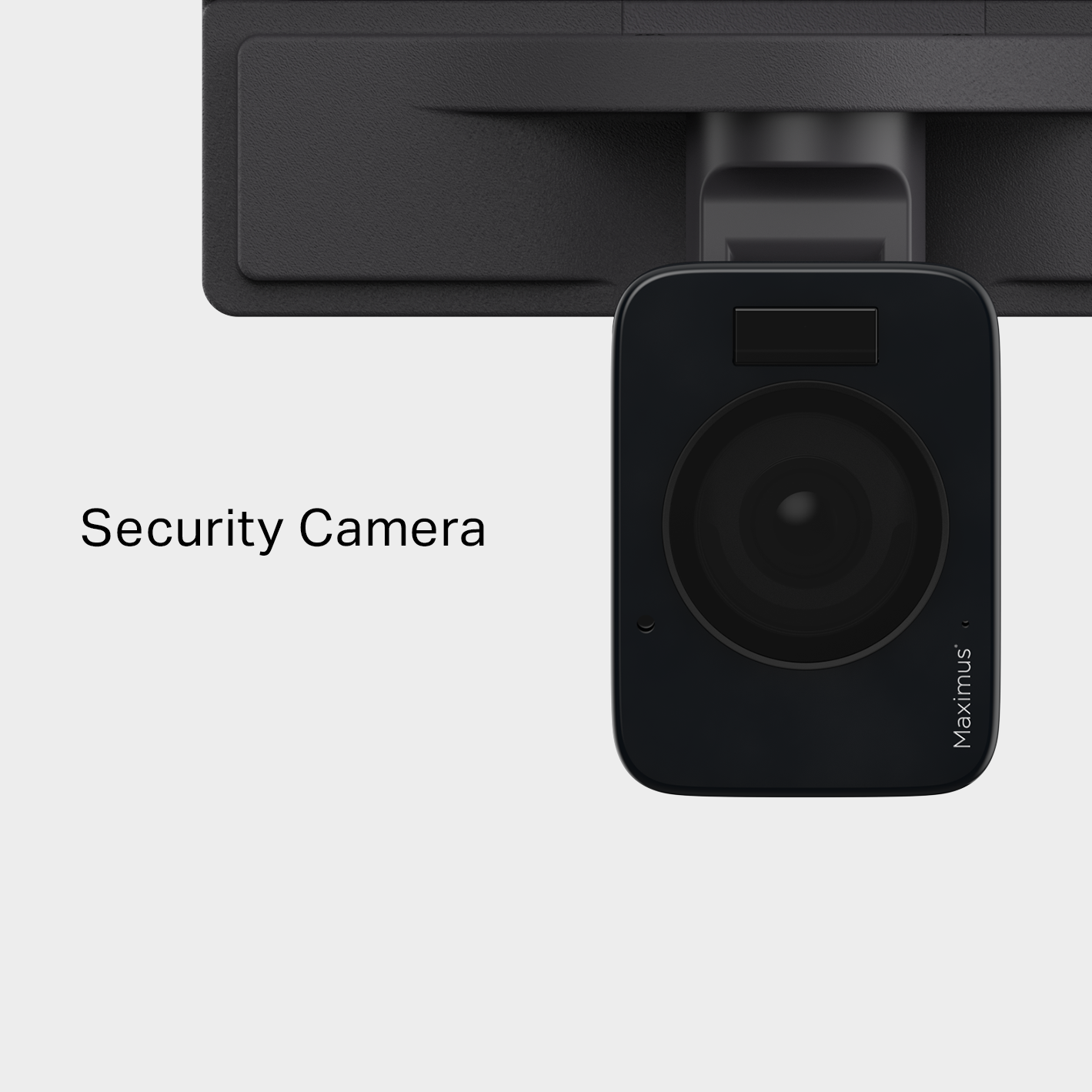
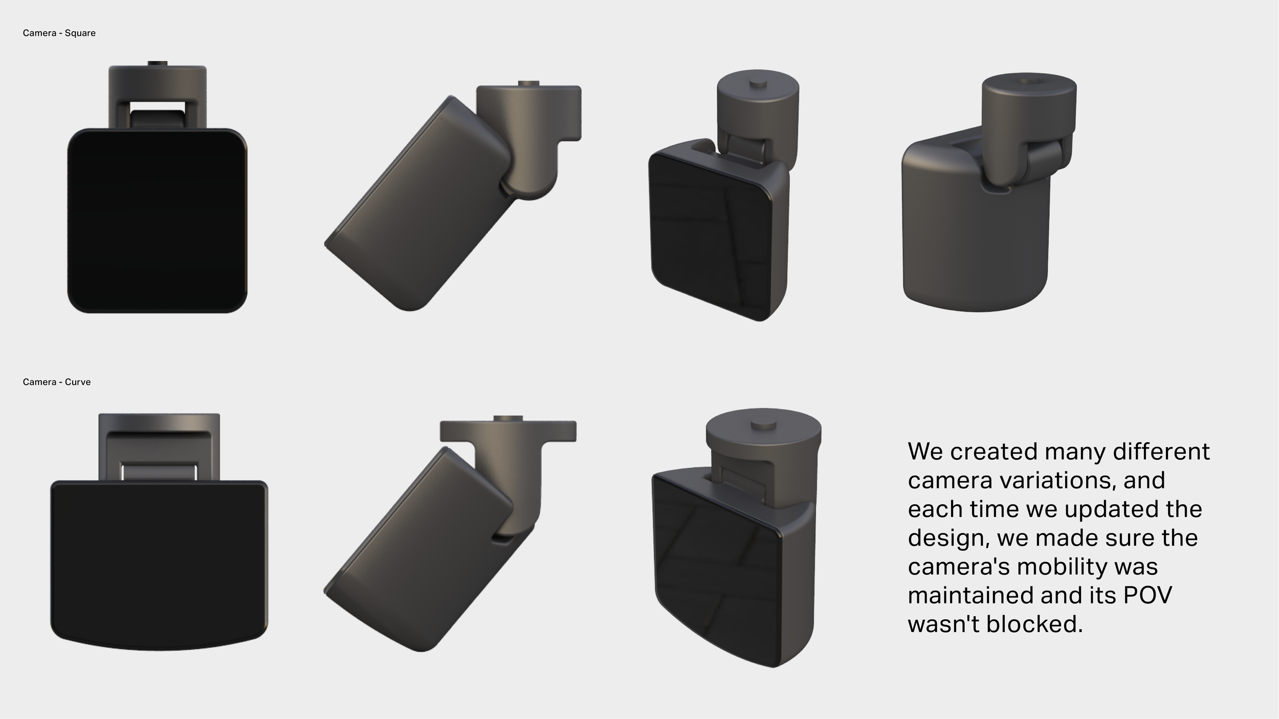
What if the mounting block combines with a security camera?
The universal wall plate camera. Designs for various outdoor lighting and home styles.
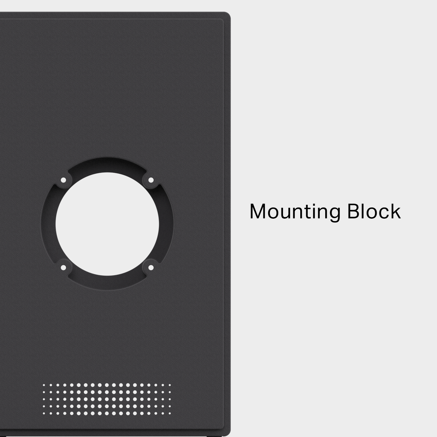
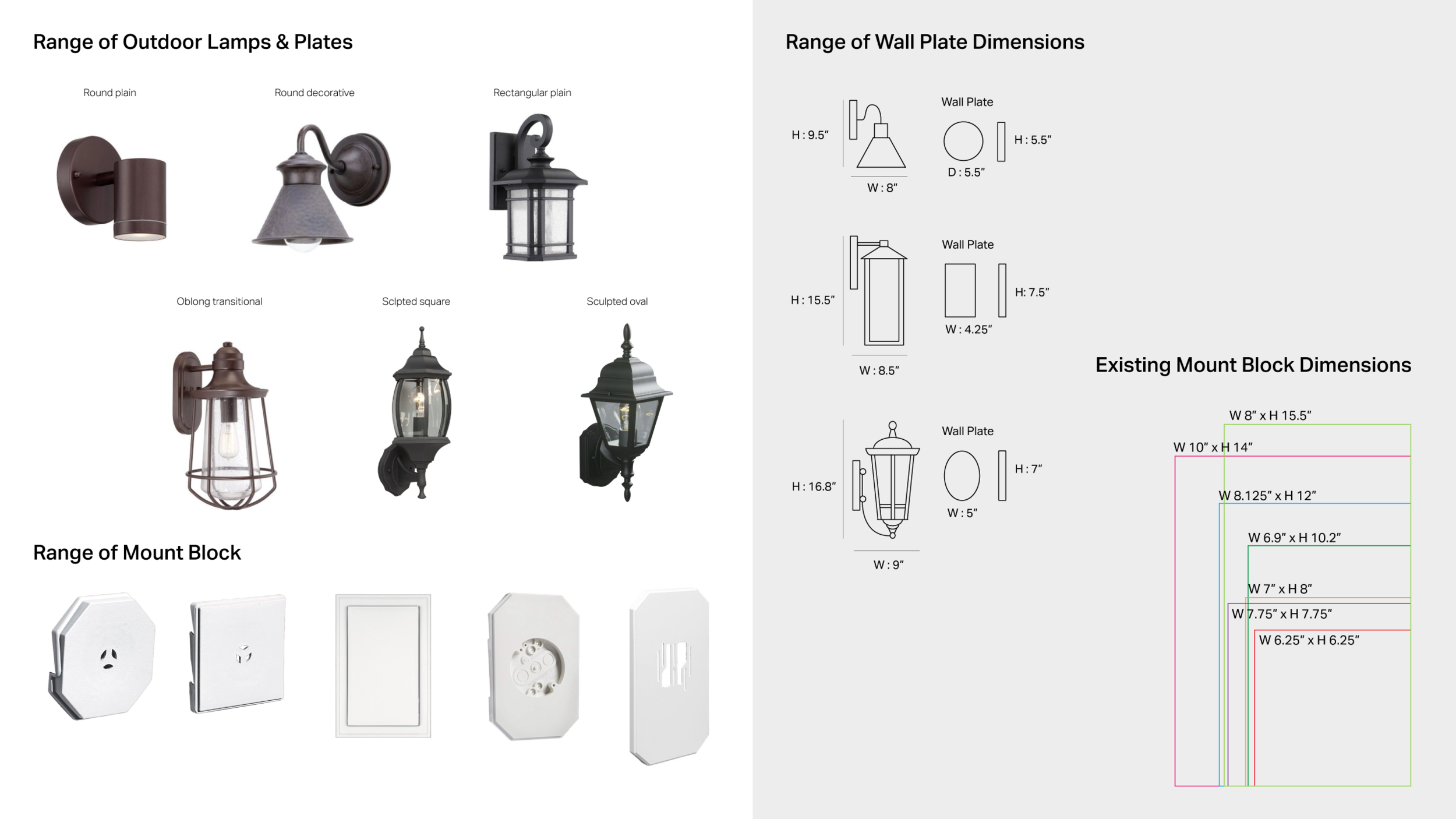
Mounting Block
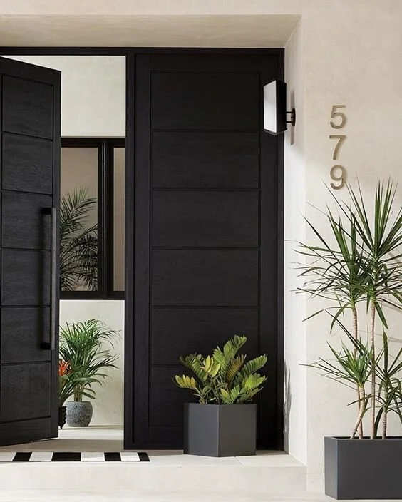
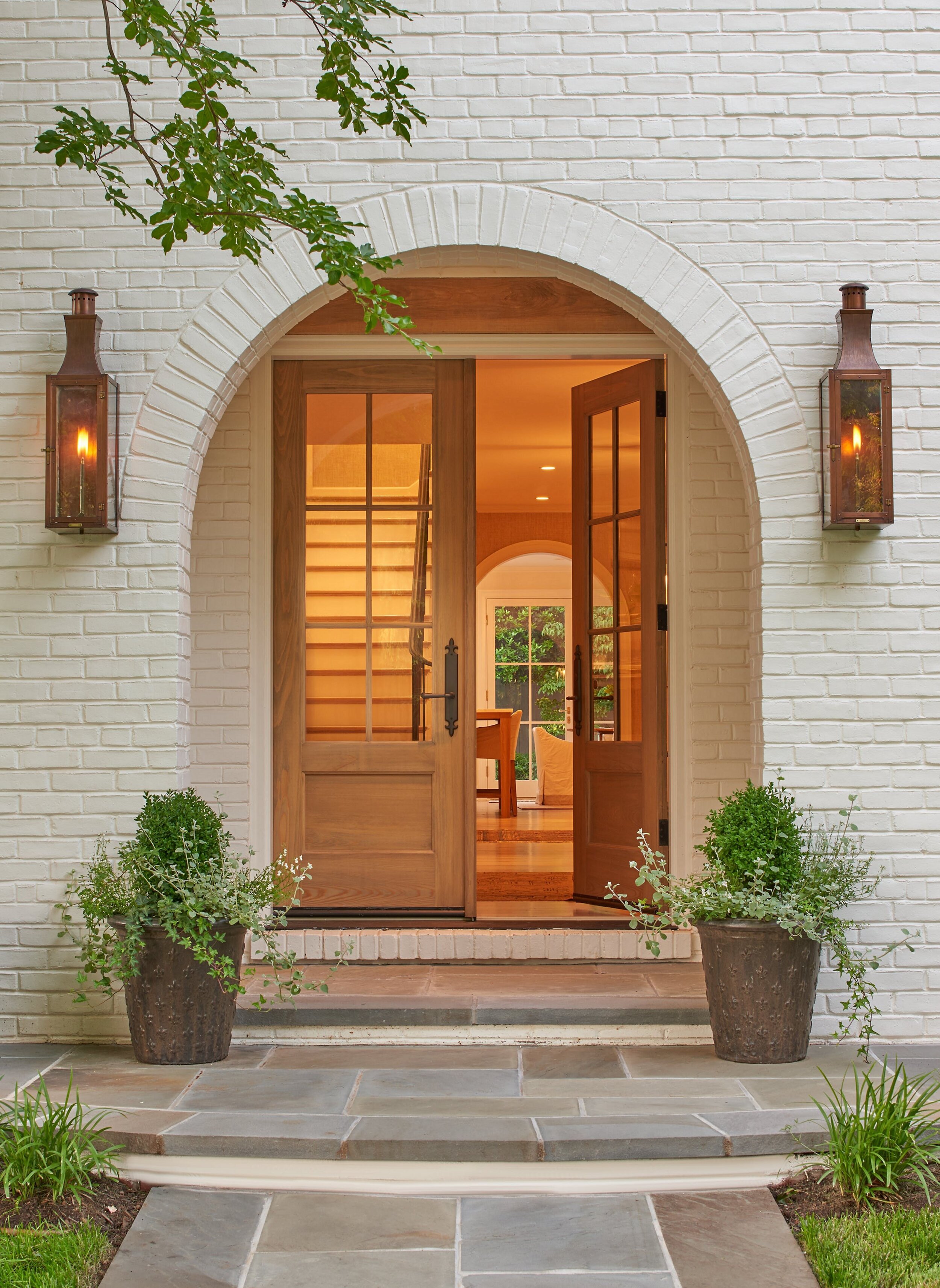
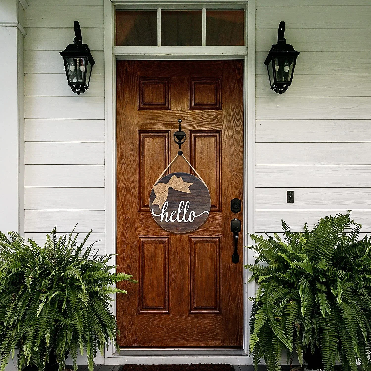
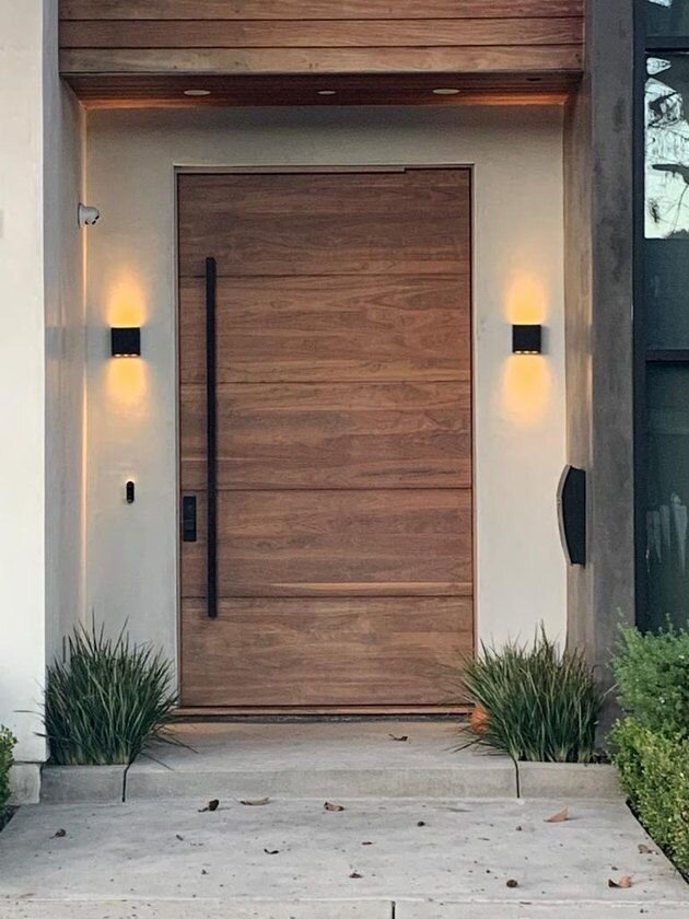
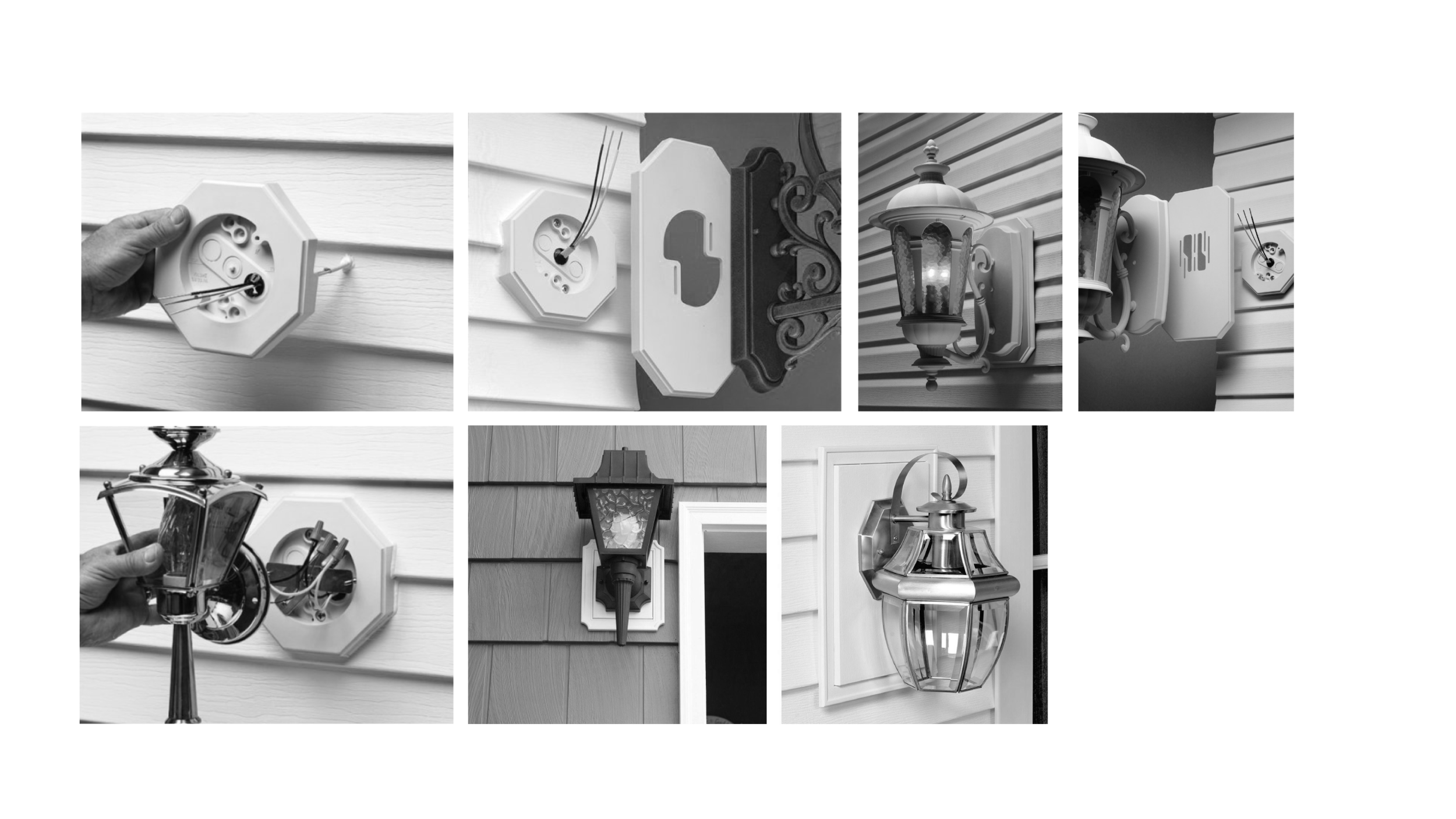
Mounting blocks are ideal for concealing cut ends and providing a flat, uniform surface on lap siding or stone to mount fixtures, outlets, spigots and more.
Conceal unsightly cuts
Provide flat mounting surfaces
Work with different siding types
Are available in matched colors
How do
mounting blocks
go on the wall?
Marketing Research & Analysis
Insights:
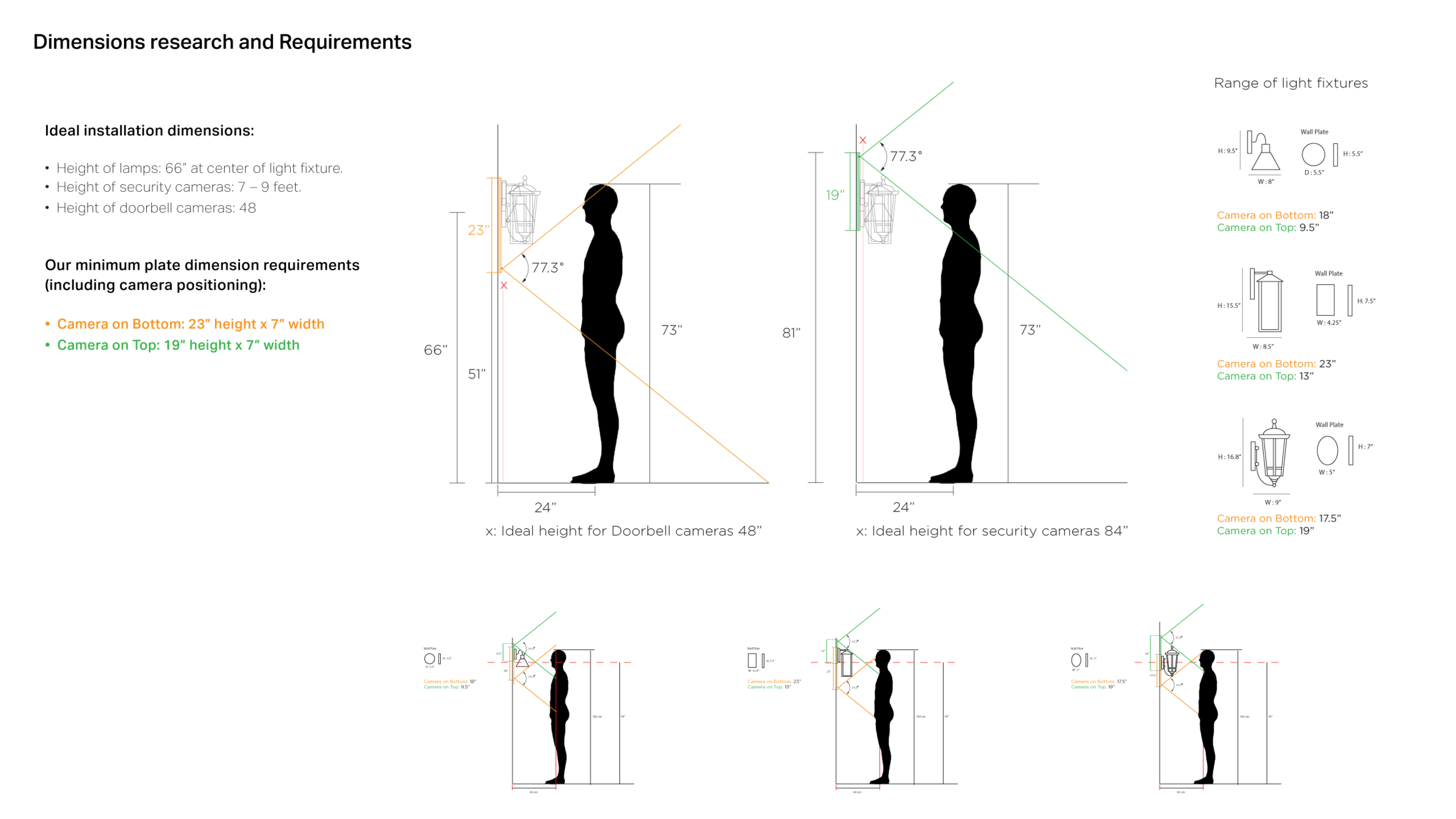
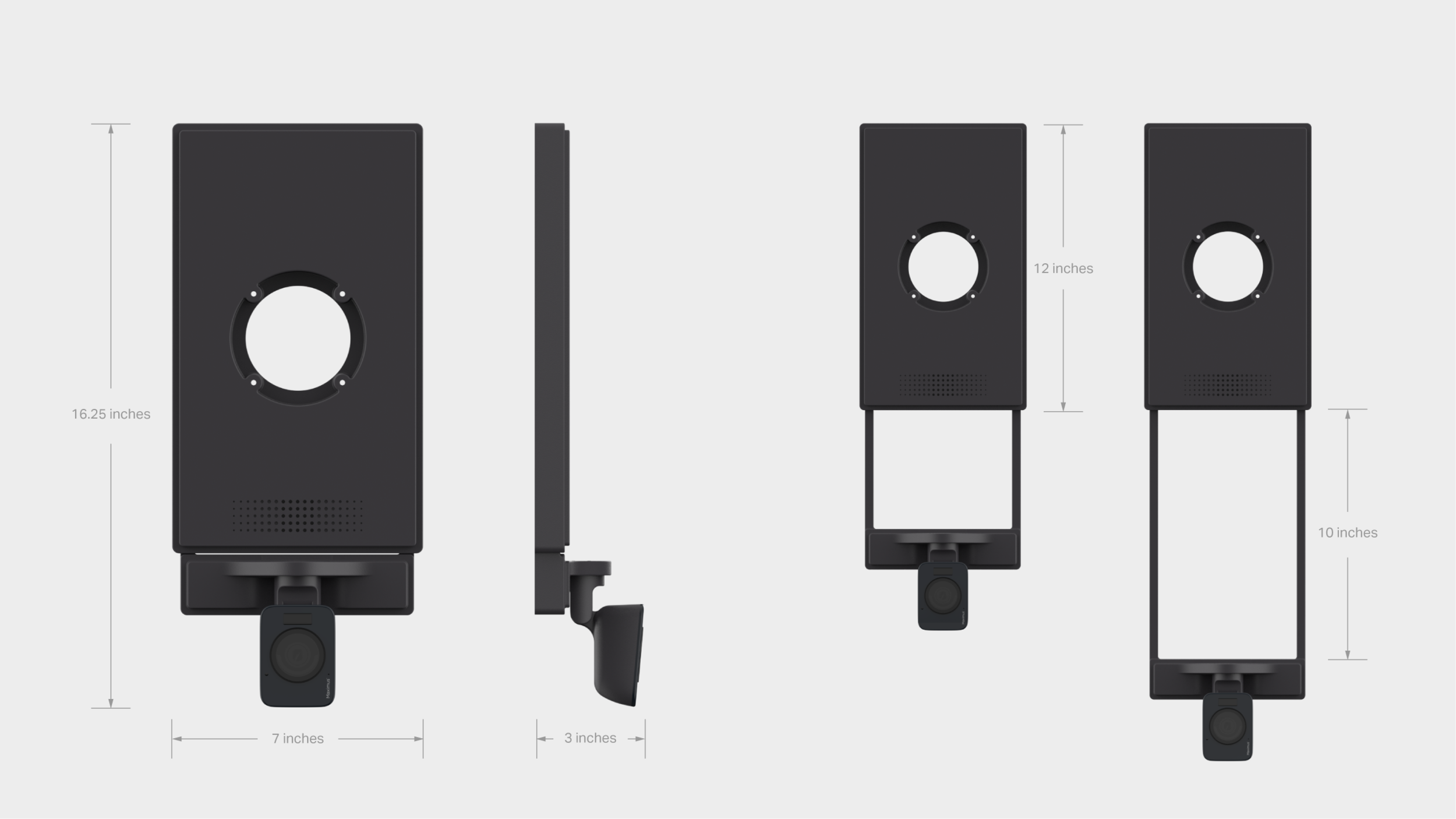
Accommodates existing fixture plates with center and off-center mounting point positioning.
Some fixture wall plates go up to 15”. We have not found a wall this tall in the Home Depot store lighting fixtures.
Ideal universal mounting plate dimension: 12 inches Height x 7 inches Width
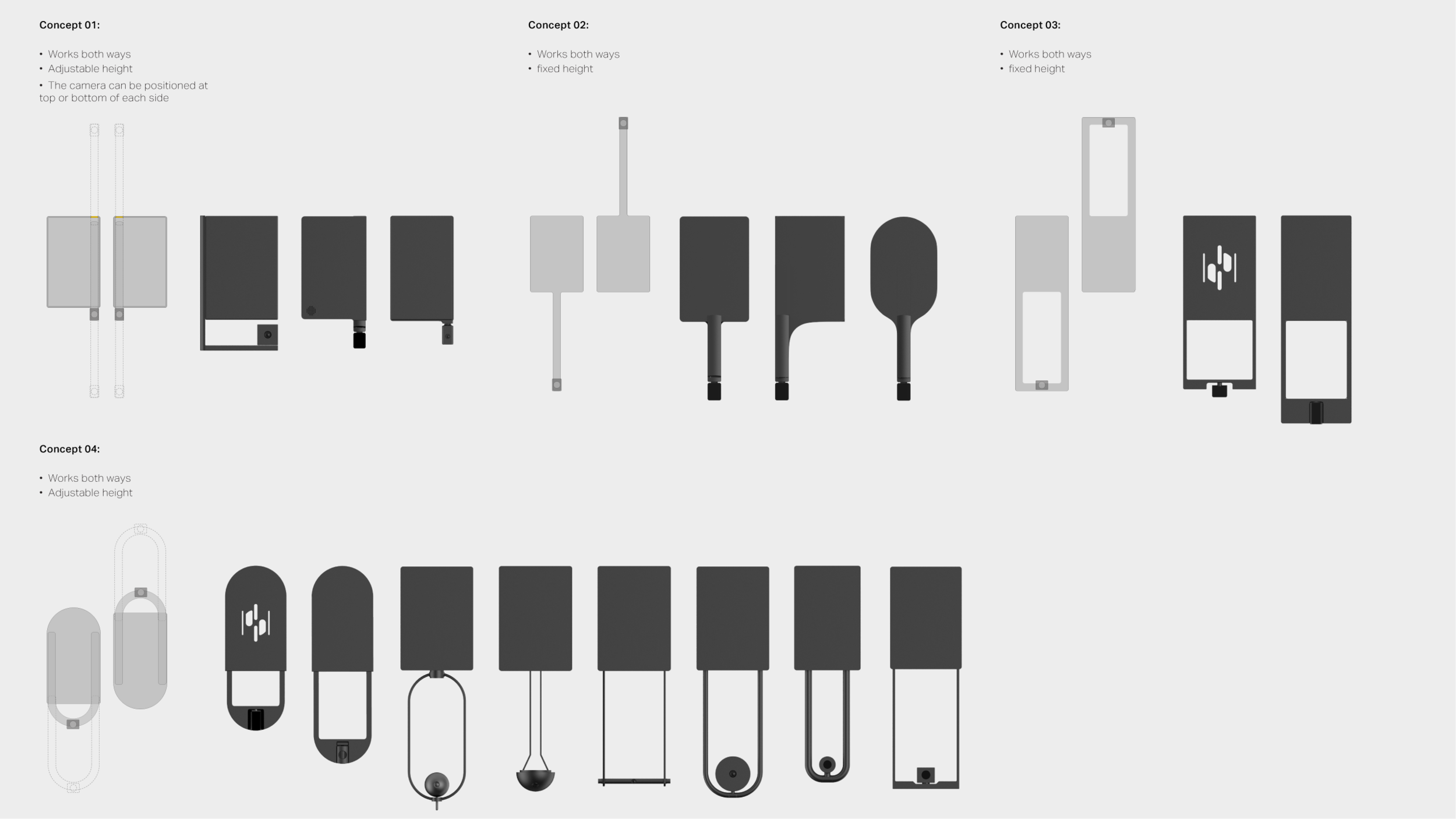
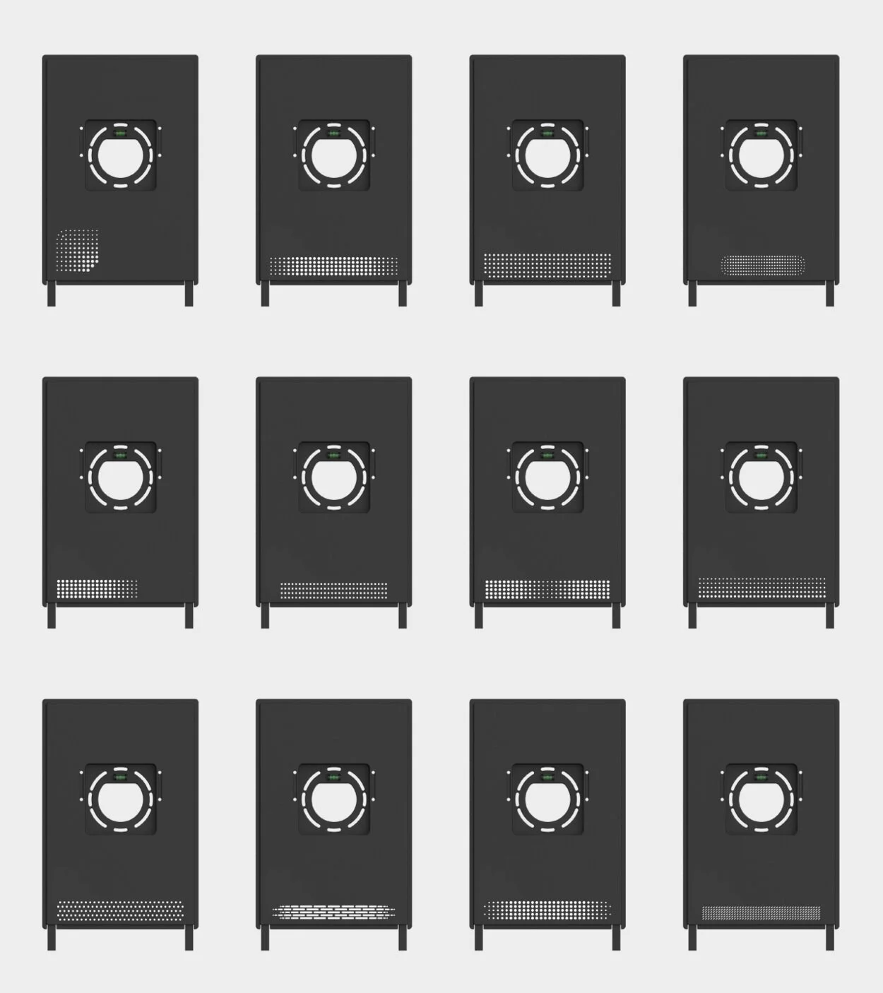
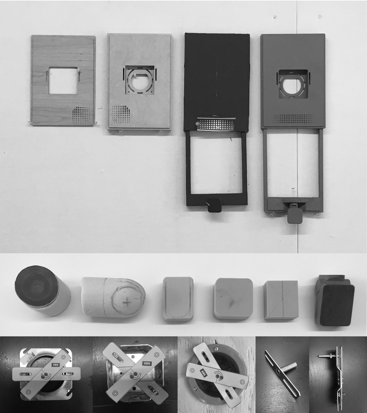
Concept Ideation Explorations
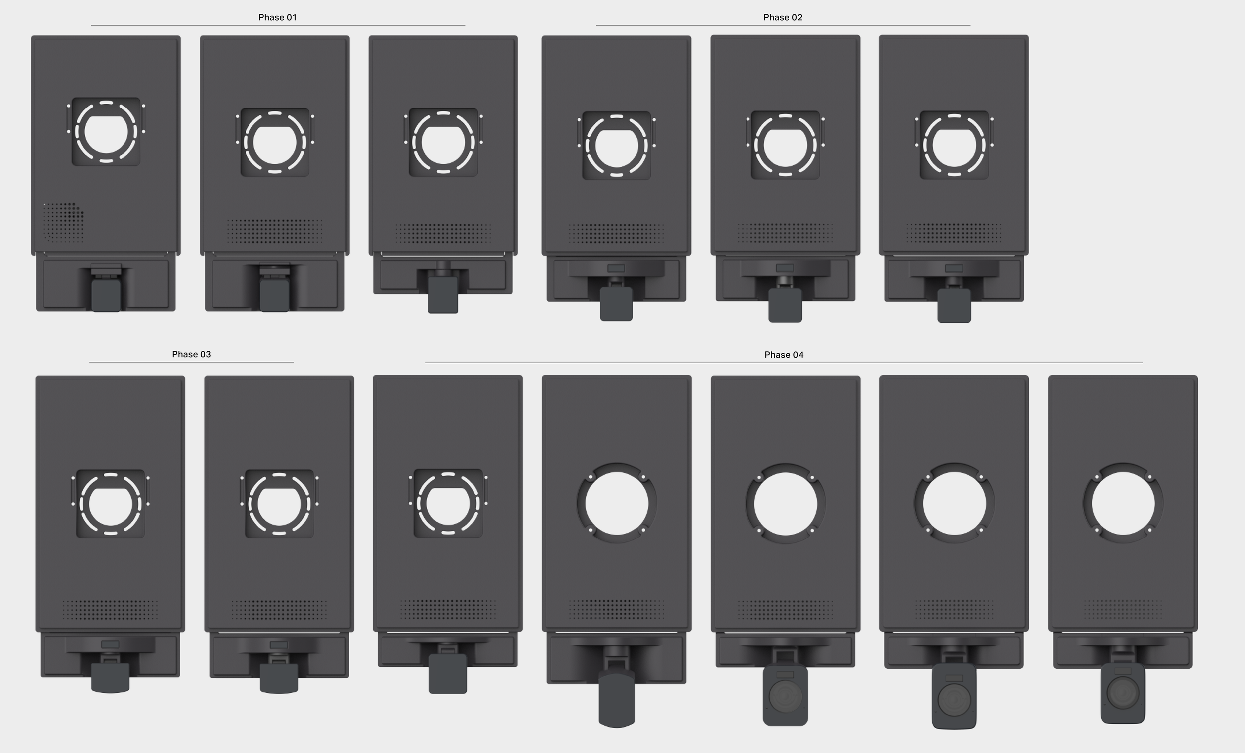
Refine Details
Installation
Step 1
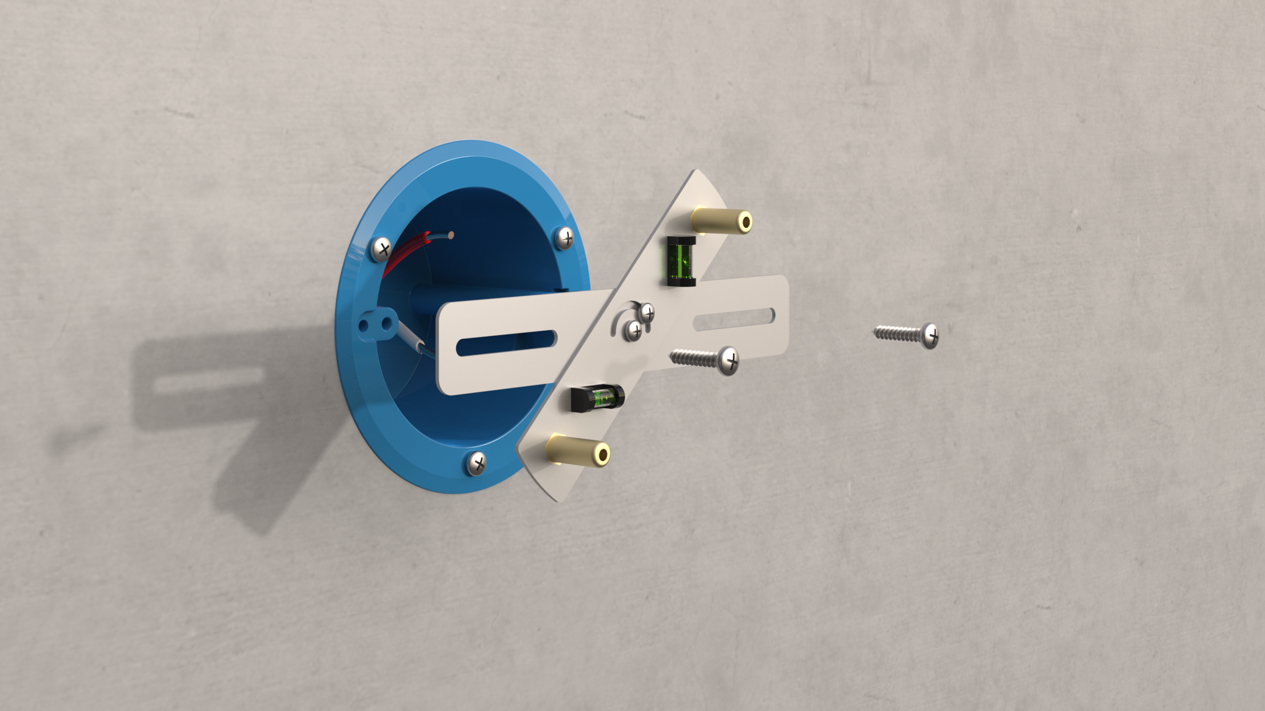
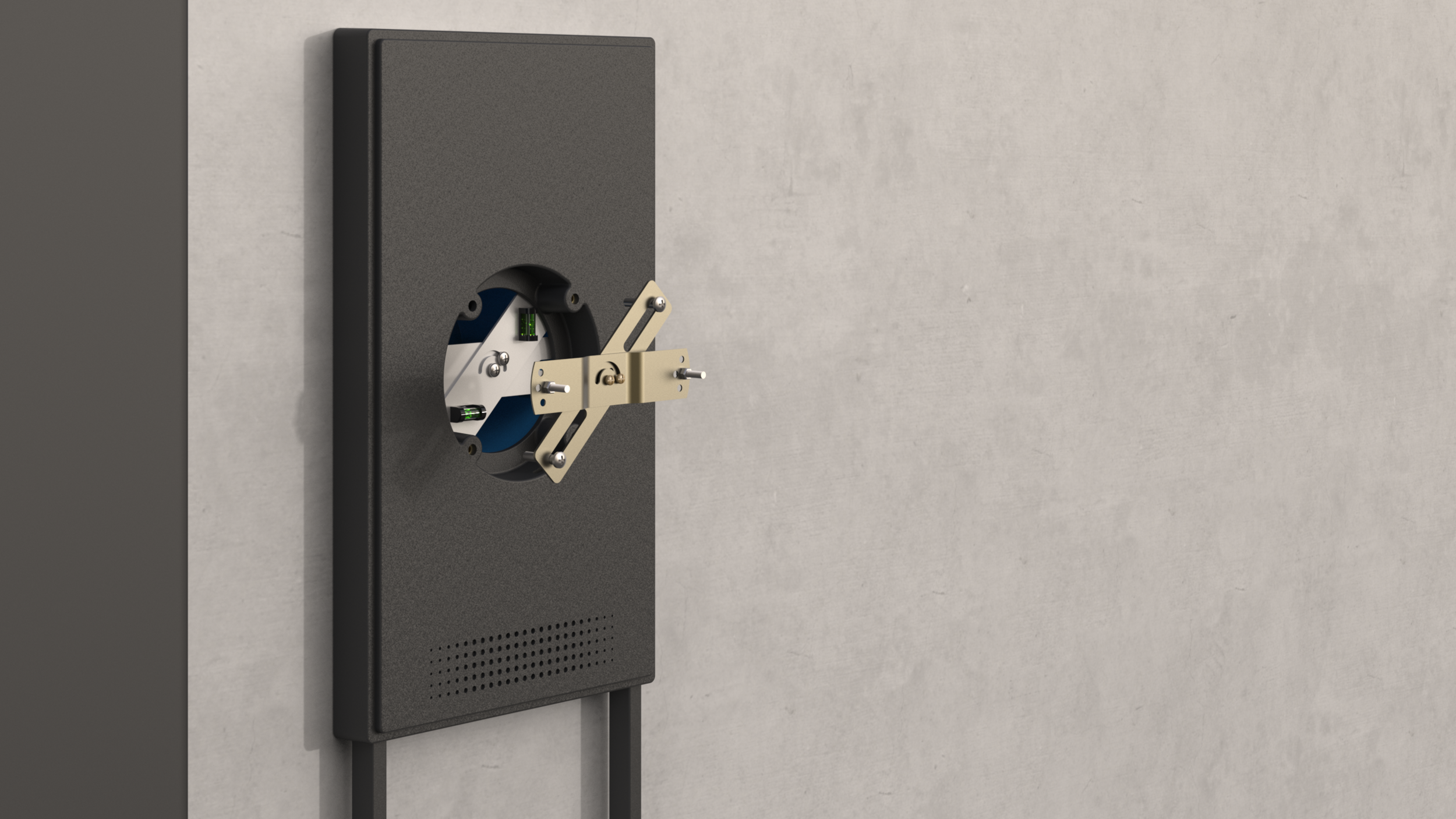
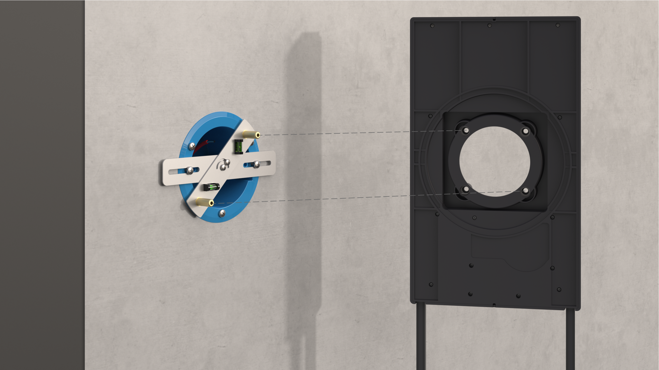
Secure mounting bracket to junction box with 2 screws. Make sure the horizontal bubble is level. This ensures the threaded pins are in the correct position (45 degrees).
Step3
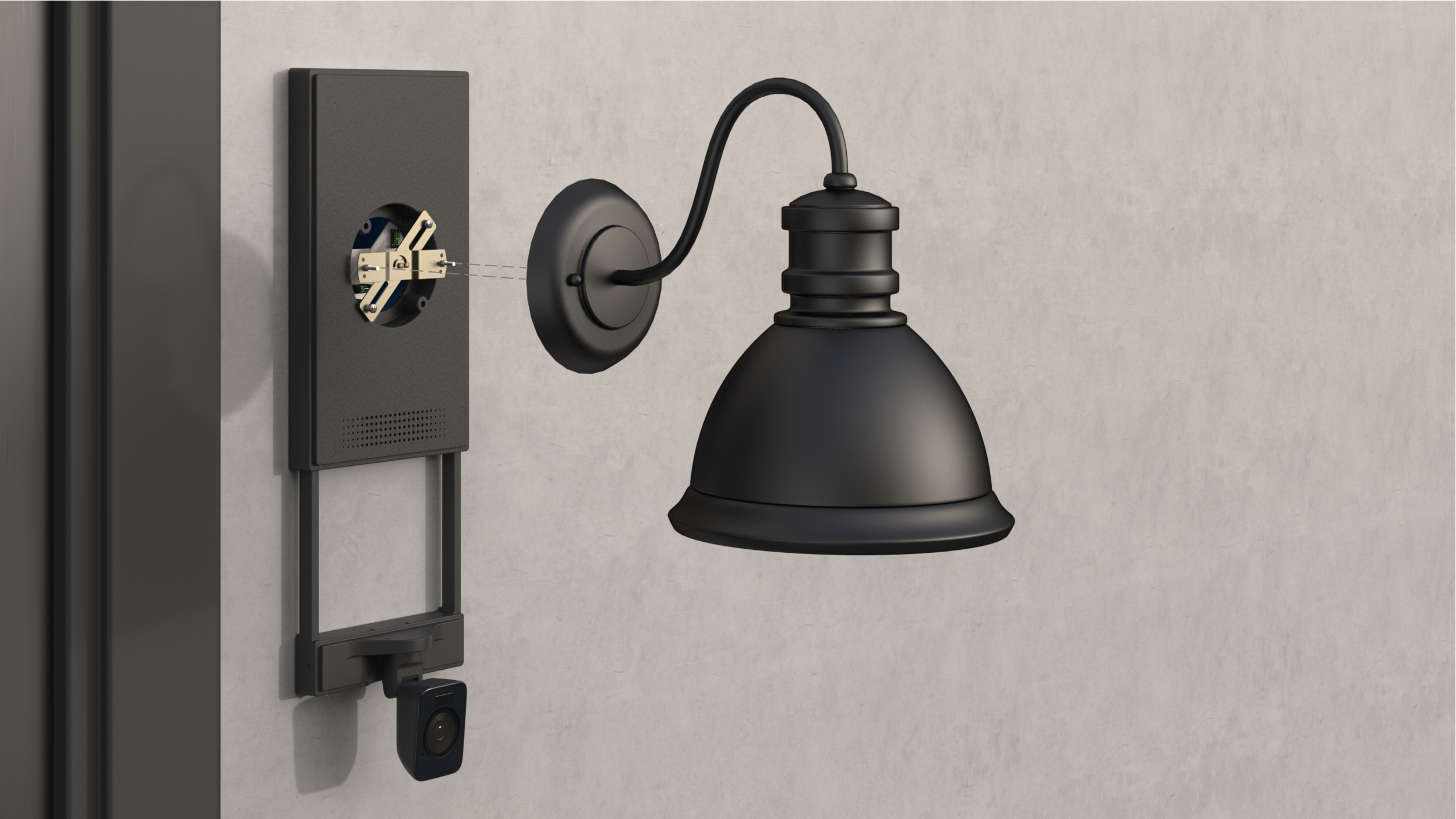
Attach cross bracket provided with the light fixture to the mounting bracket (through the holes in camera wall-plate), using provided screws.
Step 2
Slide camera wall plate over the installed mounting bracket using mounting holes. The arm with the threaded pins can be reversed if needed.
Step 4
Adjust light fixture screws and attach the light fixture to cross bracket
Step 5
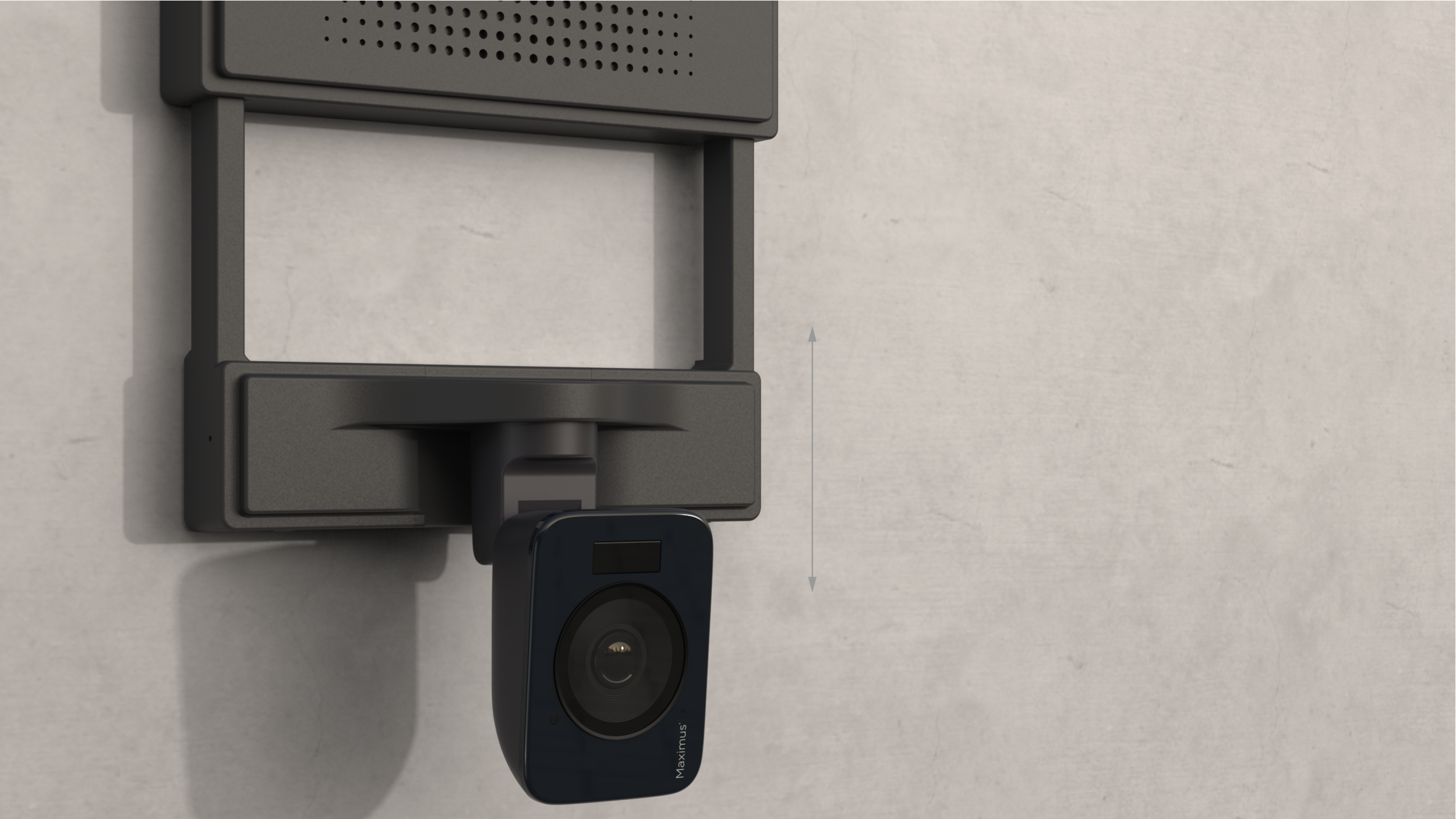
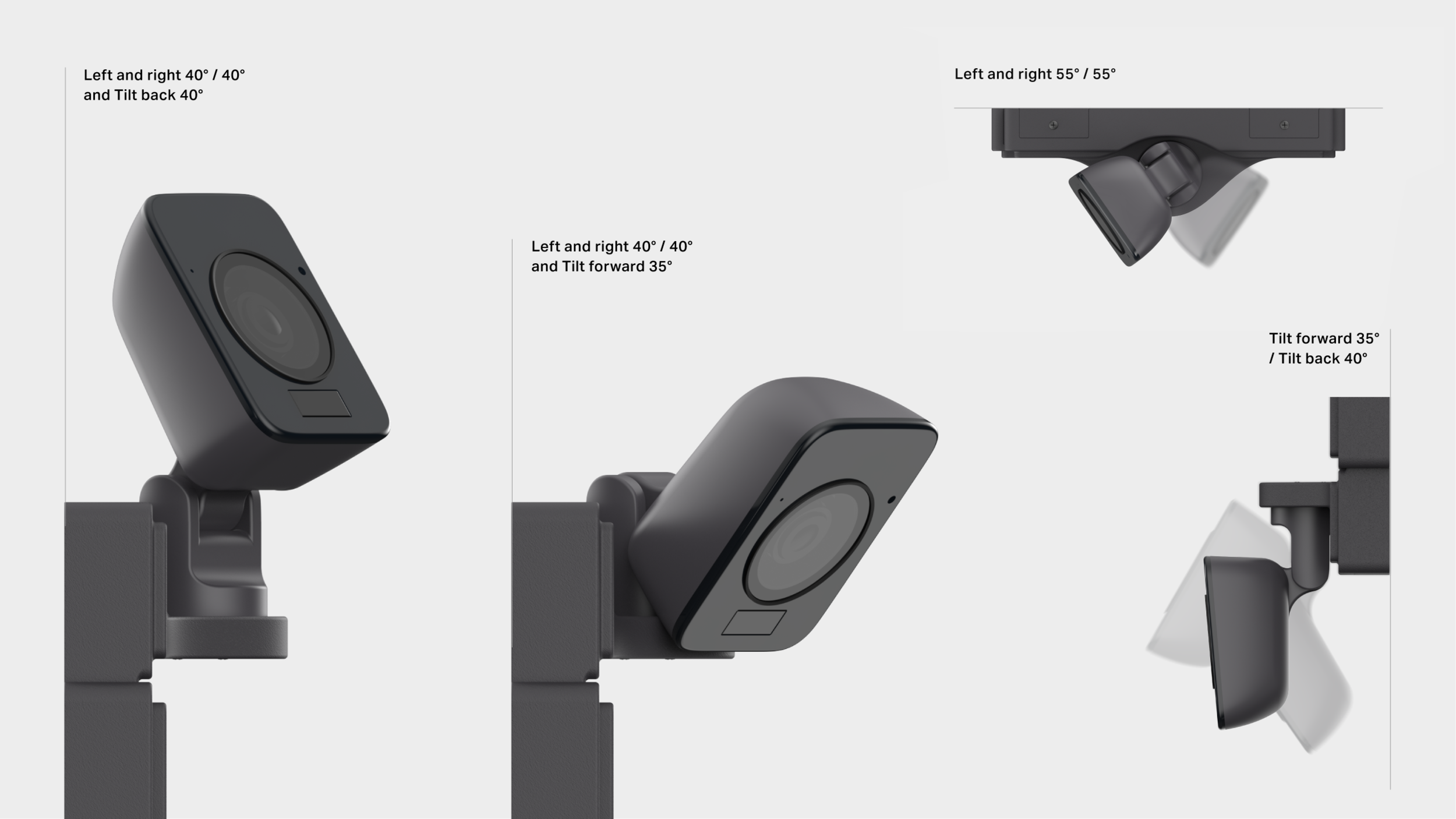
Adjust camera arm to optimize camera angle. Wall plate can be mounted with camera above the wall plate if required.
Step 7
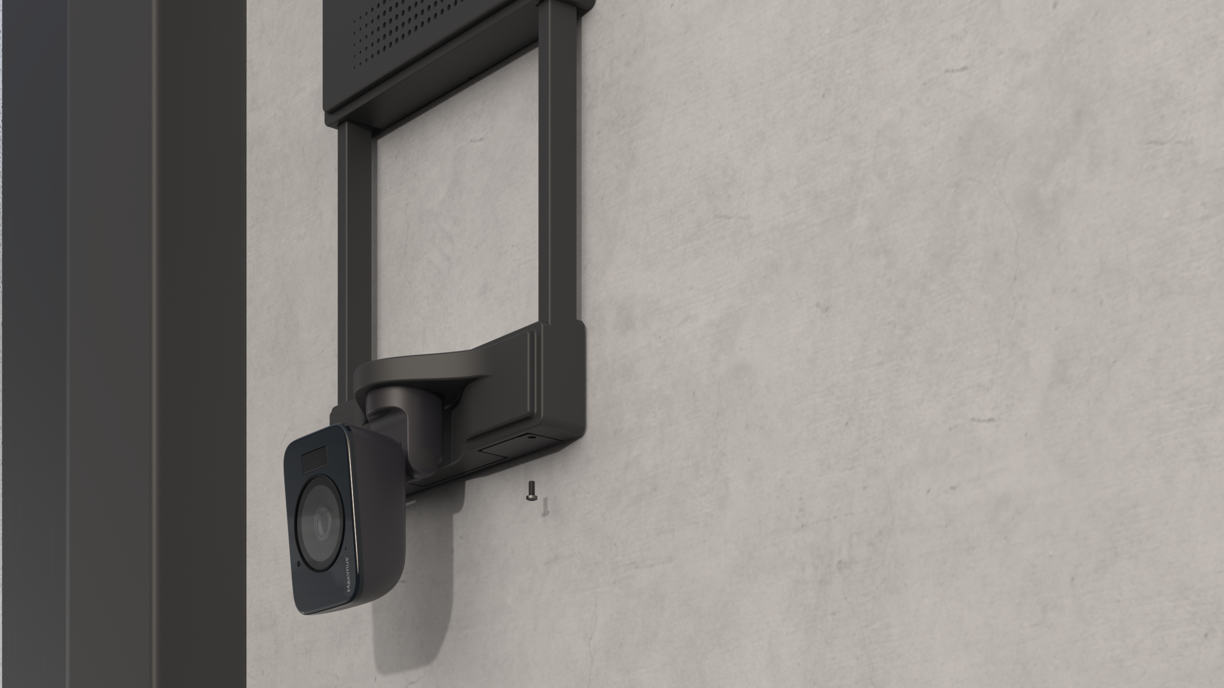
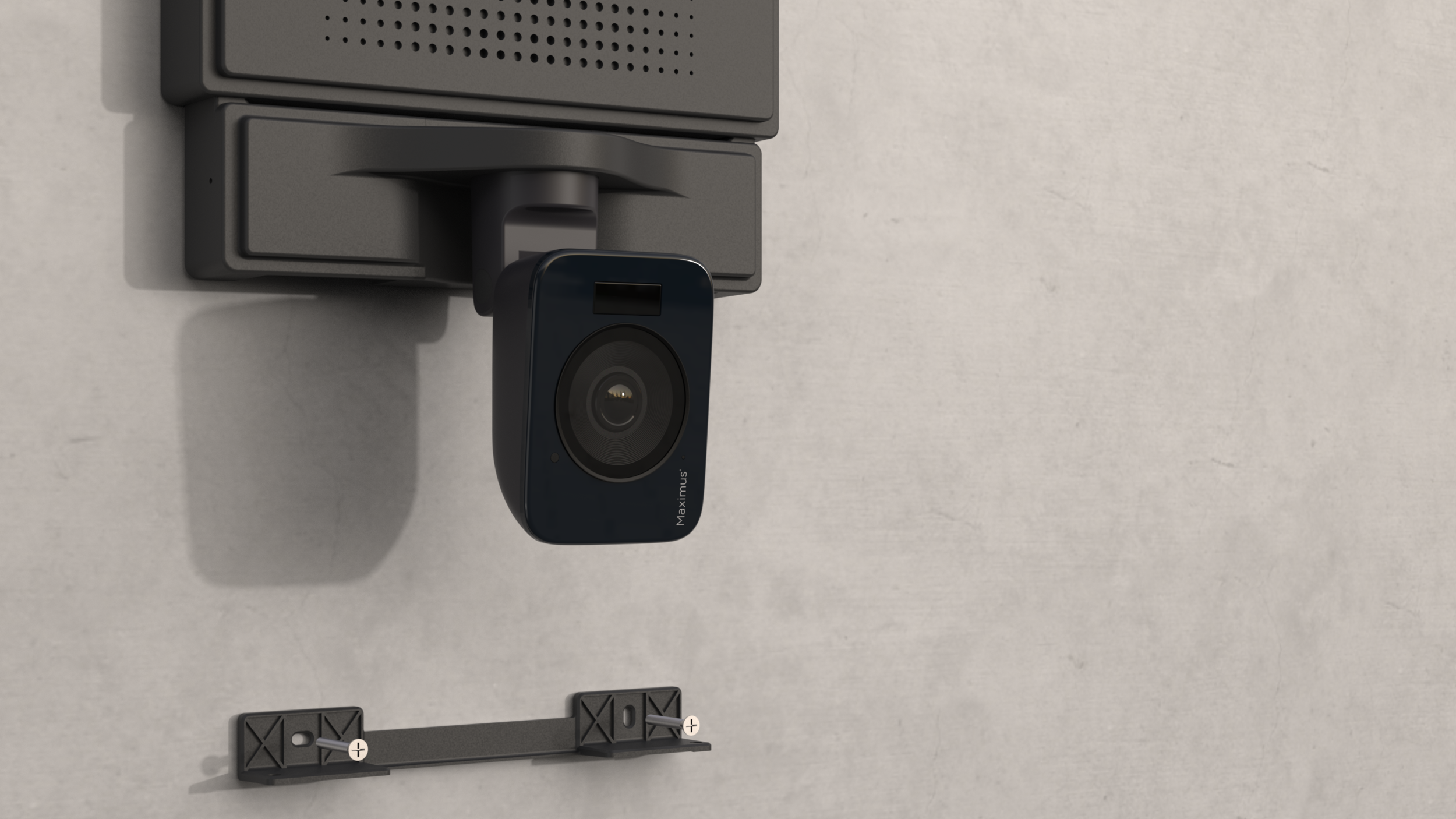
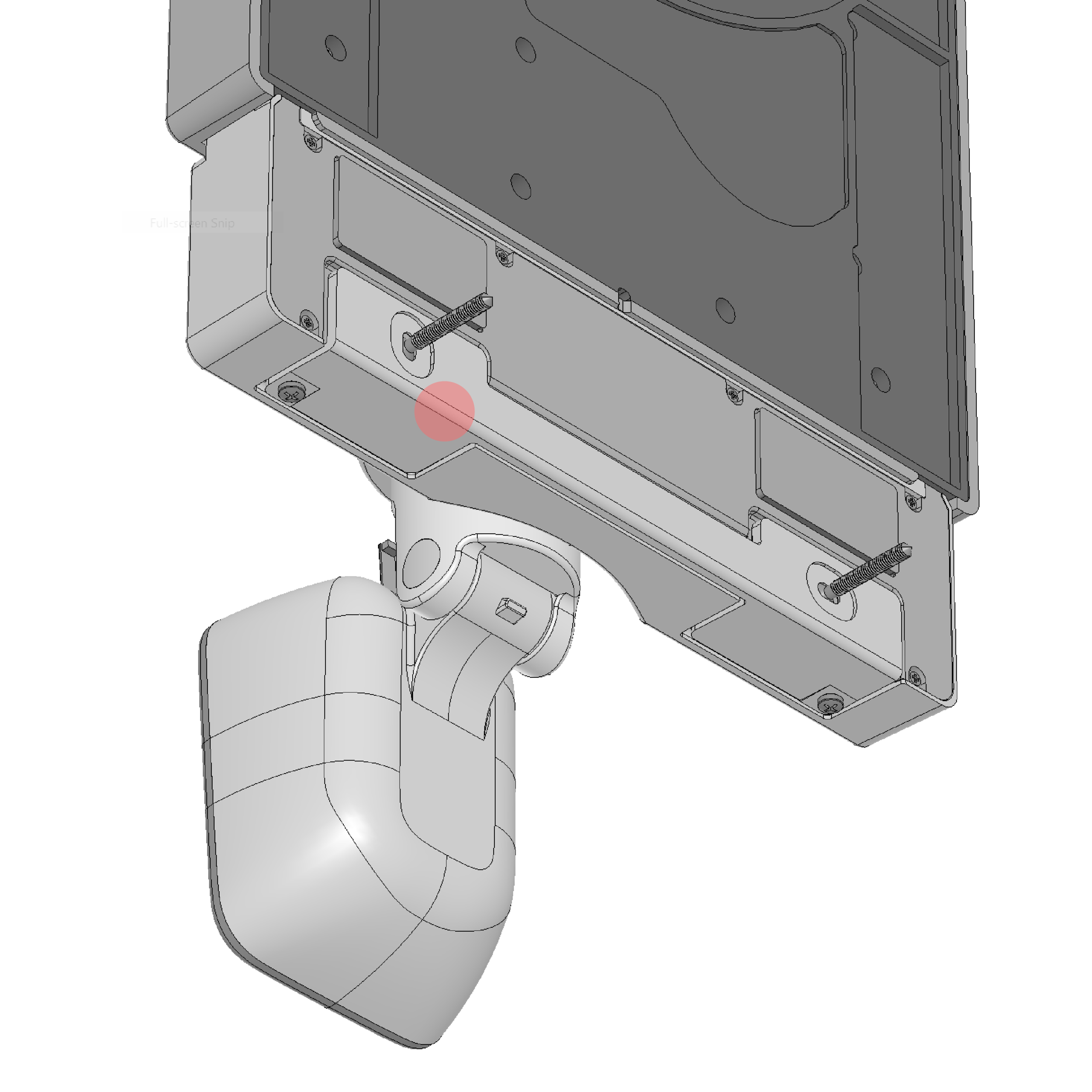
Bring camera arm back down to meet up with bracket and secure with two screws from underneath.
Step 6
Create a mark on the wall at the lower edge of camera frame. Slide camera frame up and install a bracket to the wall.
DFM
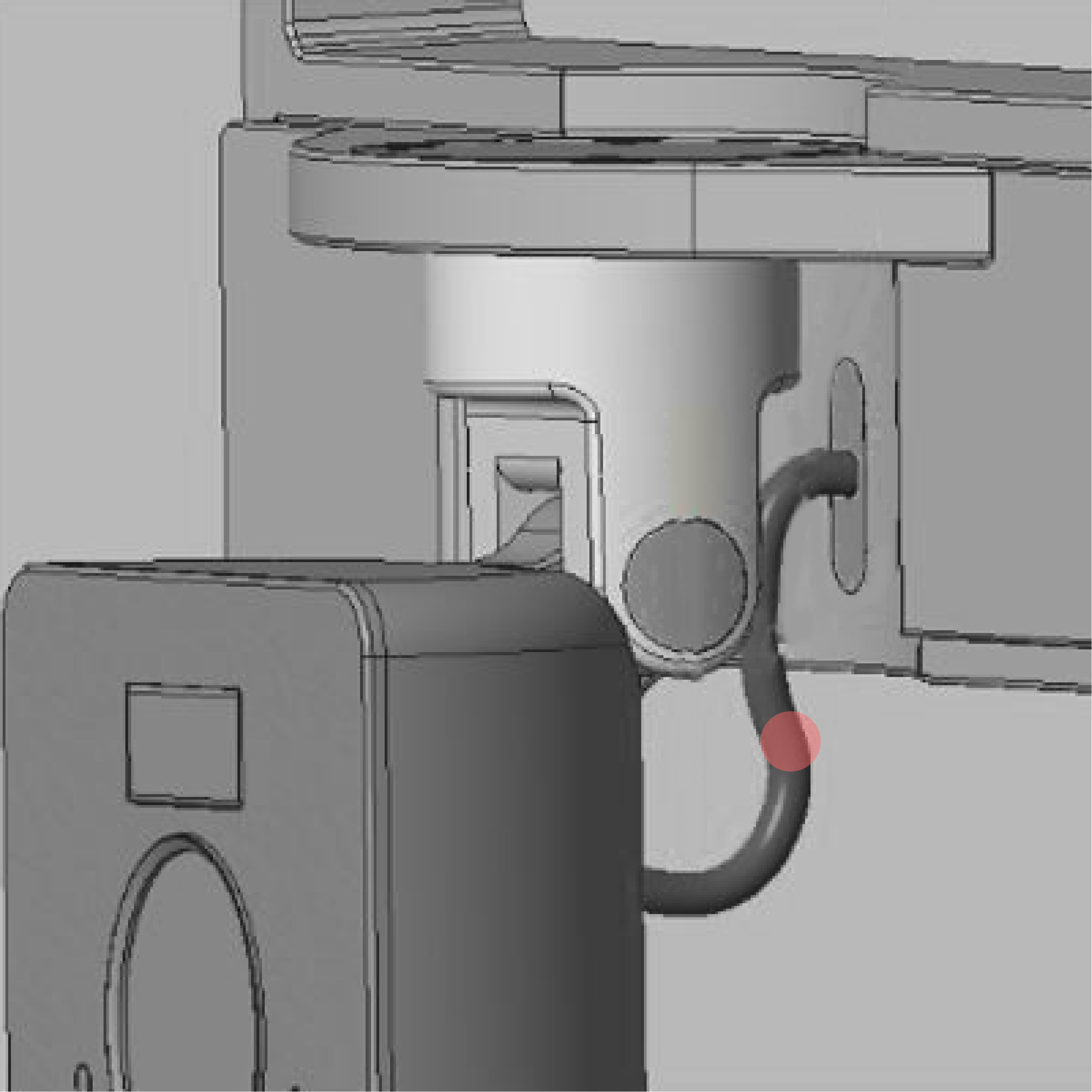
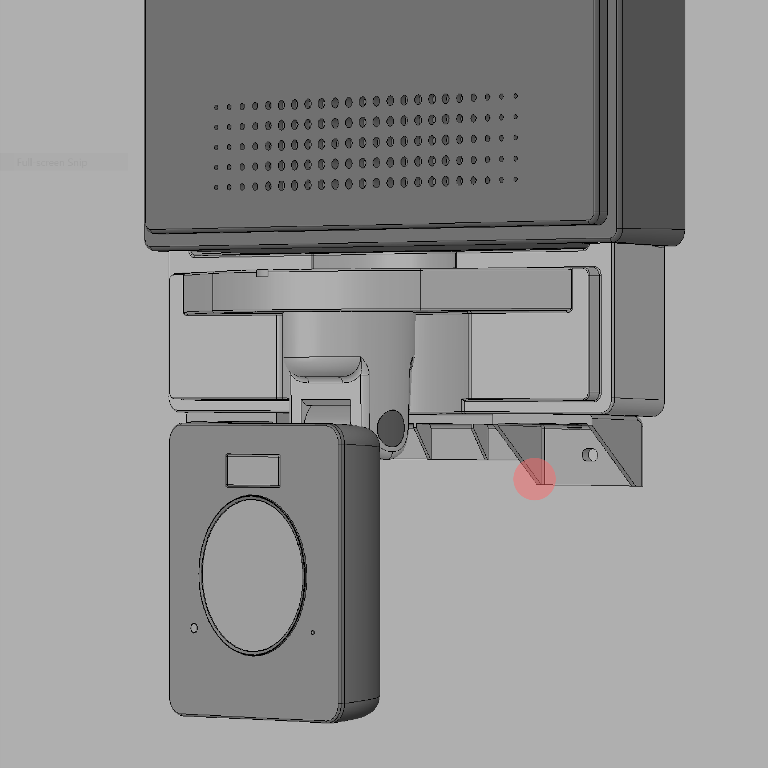
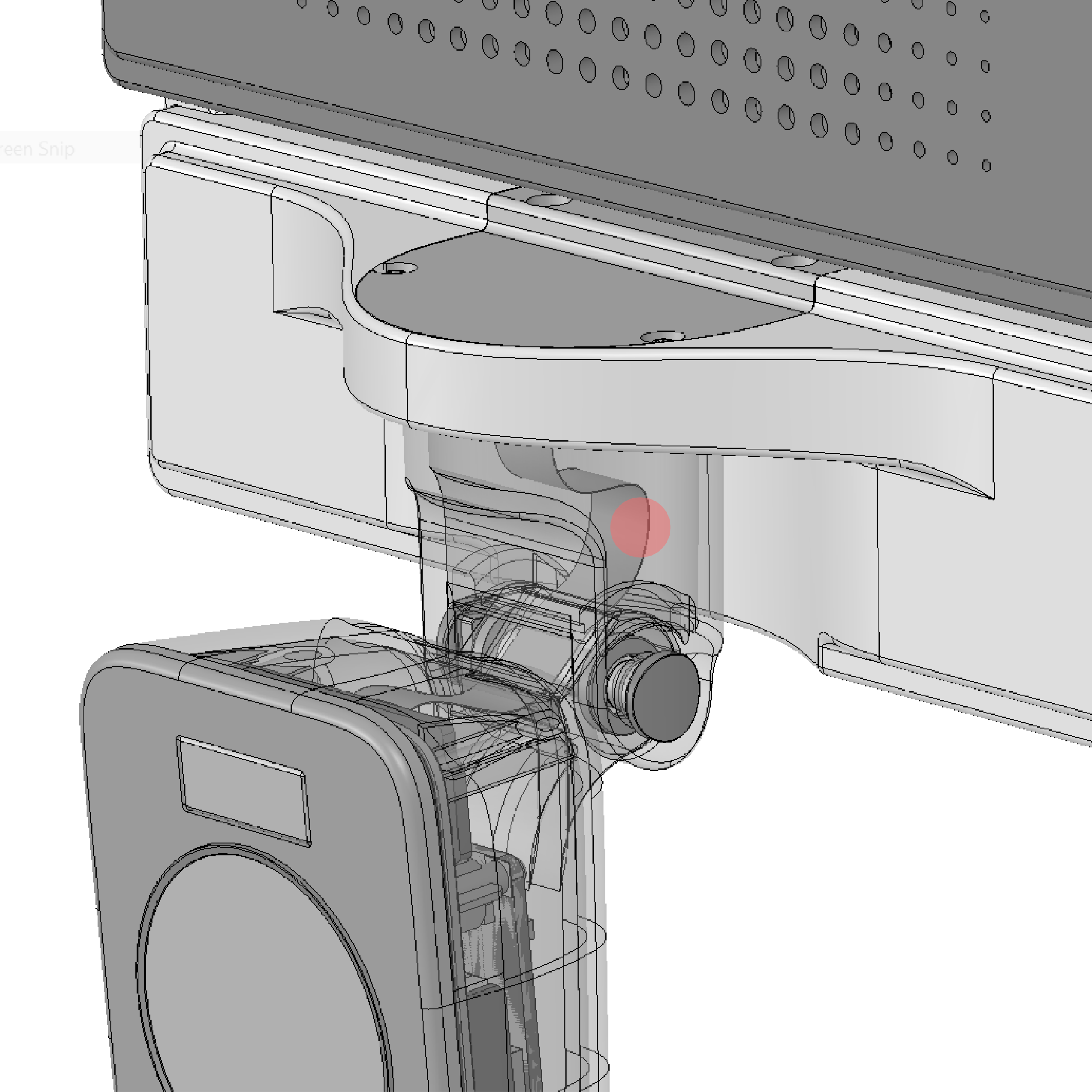
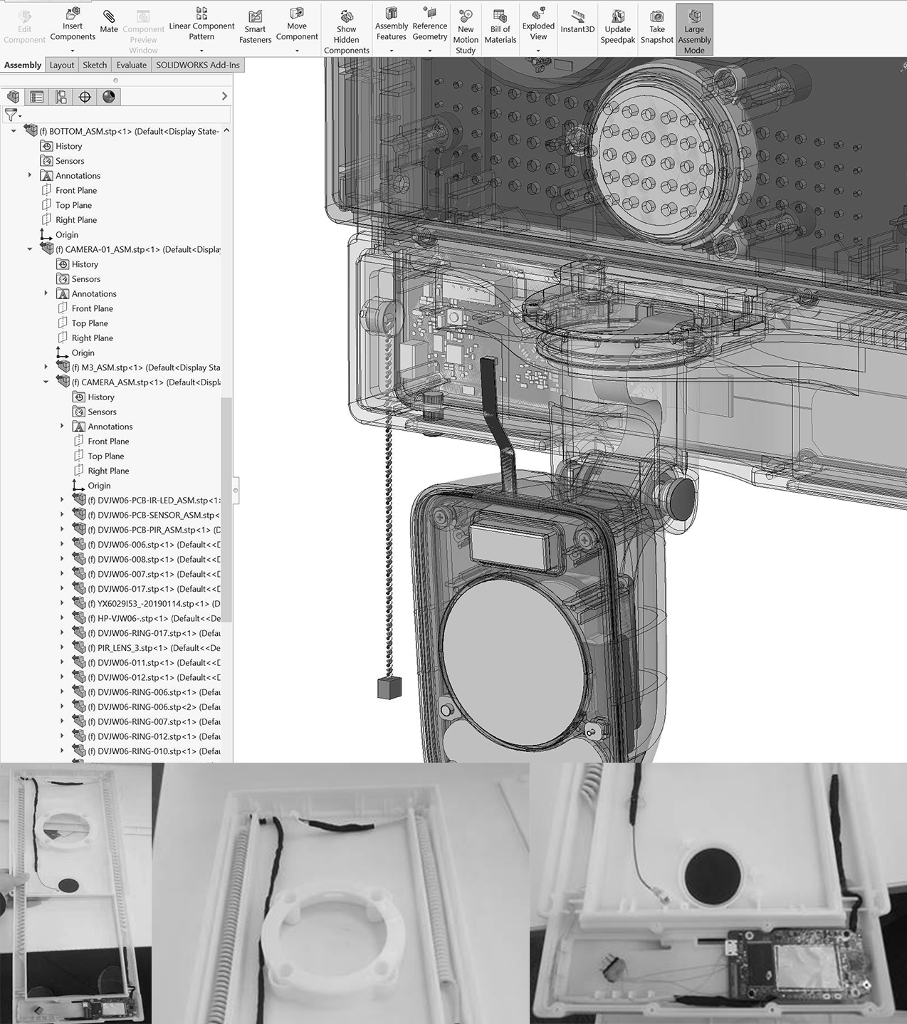
Worked closely with the engineering team to ensure all components were neatly integrated into the product and made sure the gimbal system met the client’s requirements, including being waterproof.
My suggestions to the engineering team:
The hidden wire solution.
The hidden bracket solution.
Before
Before
After
After
